| Copyrights (C) Sean Lim, 2003. All Rights Reserved |
|
Downloads - 12Tvan.zip (798Kb) - completed model
This tutorial is intended for modellers with a basic understanding of 3D modelling
for MSTS. It will be assumed that the reader has at least a basic knowledge of how to use TSM and a graphics-rendering program. The premise of this program is to take off where Matt Peddlesden's excellent wagon tutorial that came with the TSM package left off. It would be best if you have completed that tutorial once, but that is not a prerequisite for this tutorial.
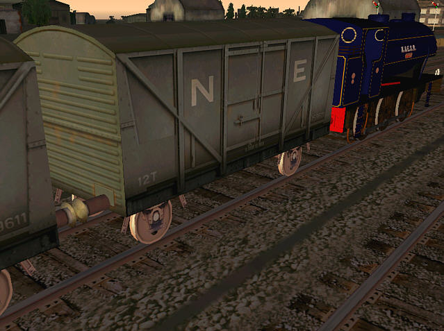
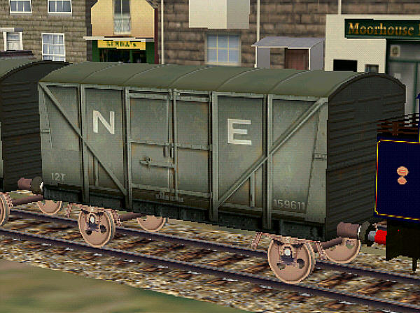
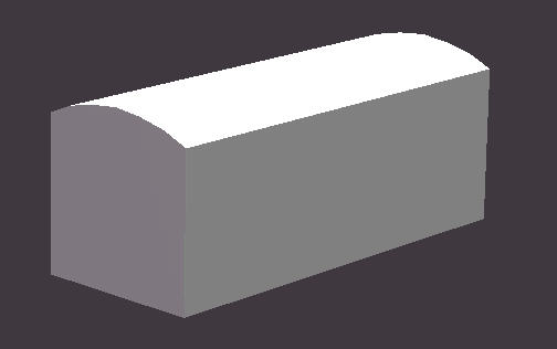
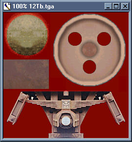
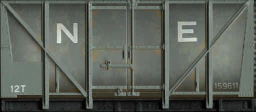
In this new tutorial, you will learn how to build a more advanced version of the wagon and how to use advance graphic techniques to finish off the texture for the model. (See fig 1.)
The two programs used in this tutorial are:
TrainSim Modeler Version 1.1
Micrografx Picture Publisher 8.0
The latter program is no longer available, but any good graphics package, such as PSP7, can be used to equally good effect. There is a download associated with this tutorial which can be found in the download area of this site. If you have not done so, get hold of a copy of that file.
Hereafter, the programs listed above will be abbreviated to TSM and PP8 respectively.
Create a new folder in your TS Modeller/Projects folder and rename it 12T Van. Unzip and install all of the tutorial files into this folder.
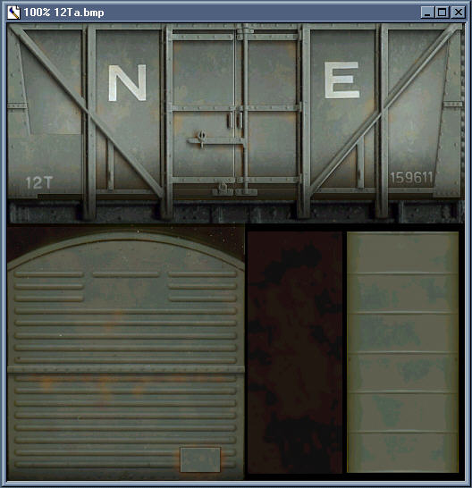
Look in the TS Modeller/Textures folder for a file called wagontut.bmp. Copy this file to your new project folder and rename it 12Ta.bmp.
Start up TSM and open up the Applications Preferences dialog box. Make sure the unit of measurement reads "Feet".
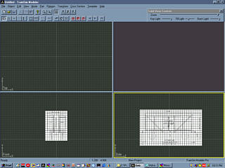
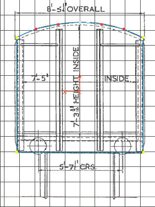
Install the plan drawings included in the tutorial download. 12Tend.bmp and 12Tside is used for the front and side views respectively. You will then need to scale each of the plans to correlate the measurements on the drawing with the measurements used by TSM. Move both plans so that they are centered on the Y-axis, and the ground lines are resting on the X and Z-axis respectively. If you do not know how to do this, you are referred back to the TSM help files. (See fig 2.)
Otherwise, on to the modelling...
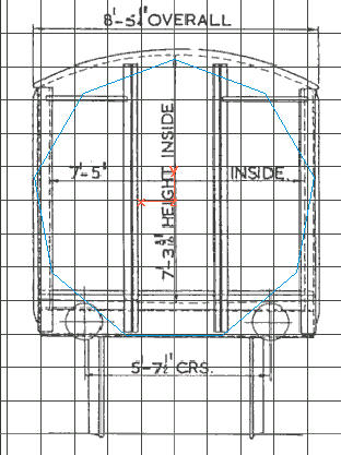
Expand the front view and have a close look at the overall form. Unlike with the original wagon, we will be building the new wagon using a 9-sided cylinder. This helps us to get a better overall shape quickly.
Create a tube along the Z-Axis that has a 4.25-ft radius and a length of 21 feet. It should 9 points and only 1 section. Both ends should be closed. Restrain movement to the Y-axis and move the cylinder upwards until the bottom end is resting on the bottom of the wagon. (See fig 3.)
It would be a good idea to save your project at this point. Name the new file 12T.dst.
Now switch to point mode and select the two lowest points. Using the scaling tool constrained to the X-axis, move these points outwards until they correlate with the bottom corners of the wagon.
Now select the uppermost point and change over to the move tool constrained to the Y-axis. Move the point to the top of the wagon profile. Next grab the next 2 points (only) and move this to the roofline. Change over to the scaling tool constrained to the X-axis and move the point inwards towards each other such that the distance between the points is approximately 1/3 the width of the wagon. You will need to move the points back up to correlate with the roofline.
Next select the next two pairs of points, and move and scale them such that they are on the roofline and the distance between them being approximately 2/3s of the width of the wagon. If your plan is out of alignment, nudge it left or right accordingly. The alignment needs not be perfect as you may find it necessary to realign the plans as you build continue building the model.
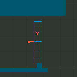
Finally move and scale the last 2 pairs of points so that their final location is at the roof/side juncture. Make sure that the sides of the wagon are perfectly perpendicular to the bottom. You should now have a perfect profile of the wagon. (See fig 4.)
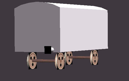
Pop out of the expanded view and check out your work in the 3D view. (See fig 5.) Deselect all points, switch back over to parts mode and open up the PART PROPERTIES dialog box (F2). Rename the part "MAIN". Next, go to the Part sub menu and Center the Axis to Origin. Save your work.
Open the Part sub menu and load the file called Rail_Reference.dsp - the rail template. You will notice that the wheels on the plans are on the ground plane. Move both plans so that the wheels are sitting on the rails, then move the wagon hull up accordingly. Re-center the part's pivot to the origin after it is moved into the correct position. Save your work.
In the object menu select the tube and create a tube with the following specifications:
Radius: 1.375
Length: 0.5
Points: 16
Sections: 2
Cap both ends and create the wheel along the X-Axis.
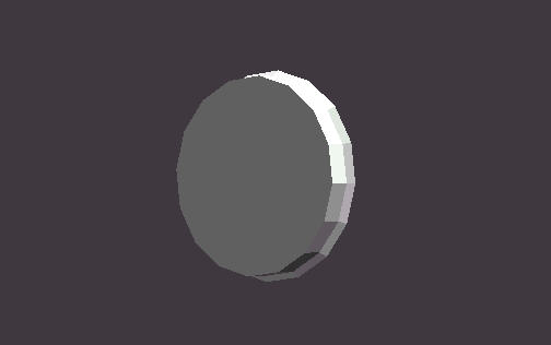
Move the wheel so it is at the level of the rail over to the right side so that it is sitting on top of one of the rails. (See fig 6.) Do not move the wheel along the Z-axis at this point. Leave it at the center of the wagon, the reason will be apparent later. Once it is in position, remove the plan drawings from the views so you can see what you are doing (press B).
Switch to the X-section tool and select the middle group of points. Move these slightly to the left so that the wheel is the width of the rails. Remember to constrain movement on the X-axis. Now select the leftmost selection of points and using the scaling tool constrained to the Y and Z-axis, expand this section to create the rim. Switch back over to the move tool, constrain this to the X-axis and move the rear section to the right till you have lost about half the width. Center the wheel's pivot point to its center. Your wheel should look like the one in fig 7. Save your work.
Now switch over to polygon mode and delete all of the polygons making up the front and back faces of the wheel. This should leave you with only the rim. Now create a square box big enough to just enclose the rim. Switch back over to select the rim and note its' coordinates in the Parts Properties box. Copy these over to the box you just created and the rim should now be in the box. Delete all the polygons that make up the side of the box. Select one of the remaining square polygons and split this from the other polygon so that you have will now have two separate square parts. Scale and move the two squares individually until you have capped the rim. The front piece should be slightly lipped over the rim. Select the 2 squares and the rim and join these. Open up the Parts Properties dialog and check the smooth polygon option and name the new part "WHEEL". Finally, re-center the wheels pivot point to its center. You should now have a perfectly square wheel. Save your work.
Create the buffer rod using a tube with the following specifications:
Radius: 0.4
Length: 1.5
Points: 8
Sections: 1
Un-cap both ends and create the wheel along the Z-Axis.
Move this into place at the front of the van on the right. Pop open the Parts Property panel and note the X and Y-axis values.
Create the buffer ends also using a box but with the following specifications:
Width: 1.25
Height: 1.25
Depth: 0
Despite the fact that the depth is 0, the box still has an edge (there should be 2 hidden ones). Go into polygon and delete these polygons. Then move the buffer end into position, using the values noted above to center the part exactly. Join the end to the support rod, and in the Parts Properties panel, name the new part "BUFFER" and smooth it. As before re-center the parts pivot point to its center.
Delete the rail reference object. This should now leave you with the wagon's body, a single wheel and buffer. It all looks a little odd now with square wheels and buffers, but polygon efficient models in MSTS involve a combination of 3D parts and texture formed part.
Save your work for now and close down TSM. Now for the fun part, the texture maps.
It will be assumed that you have some familiarity with your graphics application. In particular, you need to know how to create and manipulate masks, as we will be using a lot of them. We will also be using objects (sometimes called layers); the airbrush, blending and gradient fill tools.
Note that for those of you who are limited to using Windows Paint, none of the techniques outlined below will work. At a bare minimum, you need to have a working copy of PSP7, preferably Adobe Photoshop.
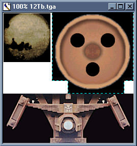
Load the copy of the texture map that we earlier renamed 12Ta.bmp into your graphics program. We will begin by editing the layout, as some of the pieces are not needed. Create a new texture map 256x256 pixels wide. Save and name this 12Tb.tga.
Crop out the buffer from the first map and move this to the new map. Put this in the top left corner of the tga map. Go to your effects menu and sharpen this image. At the moment the buffer is too green, since our final model needs to look well used we will need to alter the tone. You do this with your applications color manipulation tools.
Fig 8. - I have two copies of the buffer end. The original is on the left.
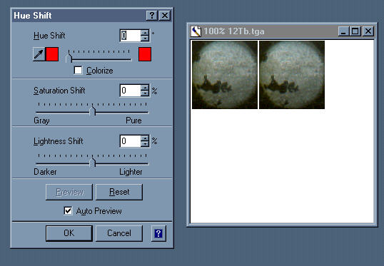
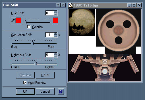
Fig 9. - Adding a bit of orange to and fiddling with the Saturation and Lightness gives me something close to what I want. It's a bit dark in parts at the moment, but there is another set of tools to fix this.
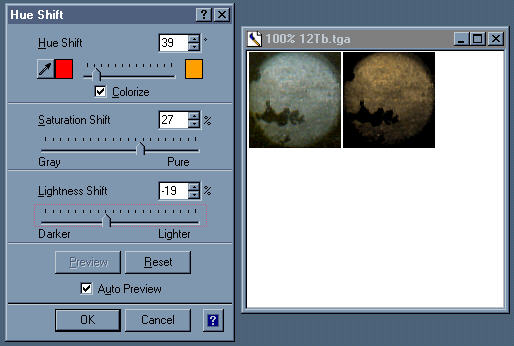
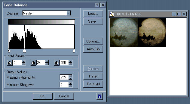
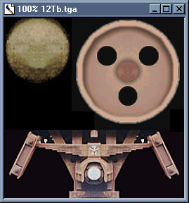
Fig 10. - To lighten the buffer without losing definition, I adjusted the median tone level. With any of the color manipulation tools, use small increments to change values. Adjusting slowly by eye till you get what you want.
You can safely flatten the copy now to the tga map.
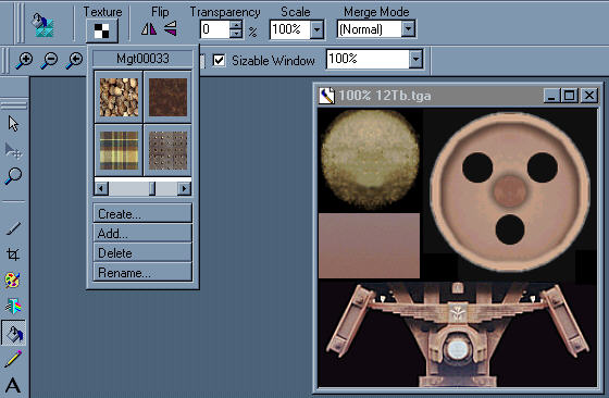
Fig 11. - Like with TSM parts, I kept a library of texture parts. The wheel for the wagon and the bogie came from other projects. The wheel was originally drawn in another graphics application and colored in PP8. The bogie is from a photograph. After some serious photo retouching, I finally came up with the fine, sharply defined image shown here. There is a copy of fig 11 in the download that came with this tutorial called 12Tparts.bmp. Load this up into your graphics application, as you will need the pieces to finish the tutorial.
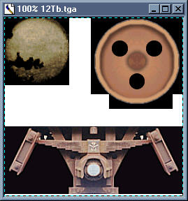
I pay a lot of attention to bogies on my MSTS models. Personally I think a good set of bogies will make a good model better and many otherwise good models are let down by shoddy bogie texture or
modelling. If you think about it, bogies are one of the key elements that identifies a train, so paying close attention to them pays in terms of being able to recreate a better representation of the prototype.
Copy the wheel and bogie from 12Tparts.bmp over to your copy of 12Tb.tga. You can fix the bogie to the map, but leave the wheel for now, as we will be working on this next.
Resize the wheel as much as possible. Then sharpen it. (See fig 12). It is good practice to use as much of a texture map as possible. I try to squeeze in as much as I can into every map I use. The less texture maps you use, the more efficient your model will be as the sim will not need to load as much data into the video memory.
The next thing we will do to the wheel is to alter the wheels colors so it matches closely the color of the bogie. This is done in exactly the same way as we did for the buffer. Go ahead and do this and fix the wheel to the texture map. (See fig 13.) Finally we want to fill up all the white space with black. This prevents the parts on the model turning white in the distance and makes the texture easier to work with.
We have a problem with the buffer end texture. Notice the big black gash on the lower left quadrant? Not much of a chance that all four buffer ends will have it, so we need to fix that. Mask off the good half of the buffer end and make this an object (layer) and flip this along the horizontal (mirror). Move this over to the left to make up the other side of the buffer end. Fix this to the main map. There will be a black hole in the middle. To fix this, mask an irregular area of the buffer that is of a similar size and color of the area. Use this to cover the black patch. A little feathering and blending will mesh your patch in with the rest of the texture. (See fig 14.)
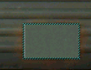
We will need a piece of texture for the buffer column and axle. Mask out a rectangle under the buffer. Using your color picker tool (this is a tool that lets you sample a color from a pixel or group of pixels) take from the bogie a dark shade and a light shade of the primary coloring. Fill the masked off area with these two tones of color, with the darker shade at the bottom. This gives you a nice clean and smooth texture piece. (See fig 15.) Problem is that its too clean for our purpose so we need to change its visual characteristics through a process called texture bumping.

Texture bumping is basically using an underlying image, such as a photograph of a piece of wood and applying it to another image so that the image would take on a wood grain characteristic. Your graphics application should be able to fill an area using a texture fill. Load up your paint can with a suitable piece of texture to use as the underlying bumping image. (See fig 16.)
Note that with PP8 not only does it come with a set of images to start you off with, it also allows you to make your own texture fills. I've chosen to use the dark brown piece at 90% transparency. It needs a couple of passes till I get the effect that I want. (See fig 17.) As always go lightly and build up. It is a lot easier to control things this way.

Last thing to do is to mask off the image to build the Alpha-Channel. You can do this very quickly by masking off all the areas in black and going back to clean up with other masking tools. Make sure that your buffer is perfectly circular, you don't need the whole thing, only about 90% of it. Also mask out the black circles in the wheel. The bogie's part of the mask needs to be cleaned up too. The finished mask should look like fig 18. The ruby red overlay is the masked out areas. These areas will be transparent in the sim.
You can save 12Tb.tga (with the mask) and close this file. This is a good point at which to take a break, as there is still a lot of work ahead.
Re-open 12Ta.bmp and get rid of the wheel, bogie and the piece above. Fill in the white spaces with black and save the file.
Re-touching the roof:
Looking carefully at the roof graphic, you will see that the left and right sides are not the same. This needs to be fixed, so mask off the left half of the roof, make the mask an object and flip it along the vertical. Fix this over the right side and combine the new piece with the main texture. If you want to, you can mask off the entire roof and texture bump it to give it a more weathered effect. (See fig 19.) I used the same piece as before to bump my map as I wanted the roof to take on a slightly rusty appearance.
The under chassis:
The bottom of the van has a bottom that will need to be covered. Mask of an are between the wagon end and roof graphics. Make this area about the same size as the roof. You can bump this area using the same piece of texture as before, or try something else. I don�t ever use pure black on models, as it appears artificial.
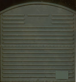
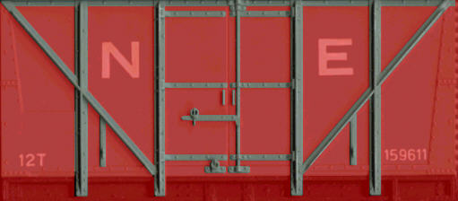
The wagon ends:
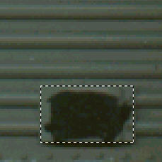
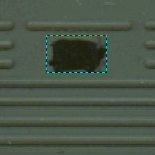
The small rectangular panel with the black smudge on the lower right of the wagon end graphic is just crying to be fixed. So mask off that area (fig 20.) make it an object and move it to the blank area near the top (fig 21.).
Using this piece as a template, create a new mask and delete the piece. Create a new piece from the mask and move it back over the original area. Do not fix the new piece. Now mask off the entire end piece graphic and bump it to give the surface a more used look. Make sure that the new version matches the roof piece we made earlier. Whilst you're at it, sharpen the image (fig 22.)
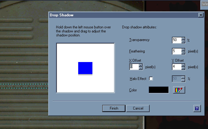
Remove the mask and mask off the metal strip in the middle and make this a separate object. We want to give this and the panel piece we made earlier a little bit of emphasis to help increase the 3D characteristics of the finished texture. There is a tool in most graphic applications that allow you to create shadows from objects. It's usually used for creating shadowed text, but in making textures for MSTS models, it has a much more useful application. So go ahead and create shadows for these parts accordingly. (See fig 23.)
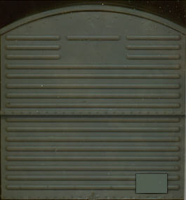
Your end piece should now look like fig 24.
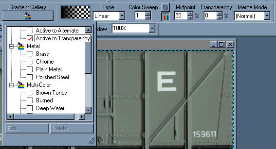
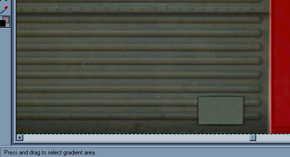
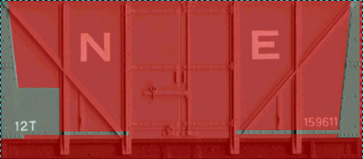
Wagon ends in real life pick up a lot of scruff. To simulate dirt on textures, there are two extremely useful tools. One is the fill gradient color tool and the other is the airbrush. The trick is in knowing how to use these correctly.
Mask off the wagon end again and make certain that you do not have the two objects that we previously created selected. Find your fill gradient tool and set this for active to transparency. In other words, when you use this tool, it fills the selected area with half the color you designate but leaves half of the underlying colors showing through - think of it like a kind of wash. You cannot use this tool at 100% strength. I normally set the selected color to about 75% transparency. (See fig 25.)
Also learn to control, even within a masked area, the amount of area affected. In this case, I will only affect changes to the area below the second lowest rib. Loading up with black and after two passes I have the effect as in fig 26.
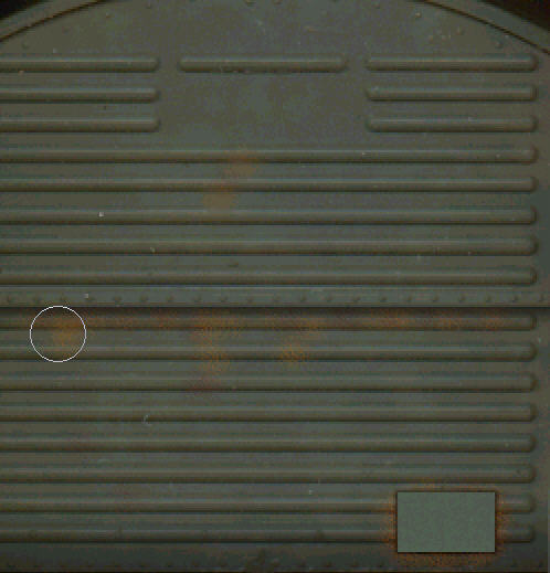
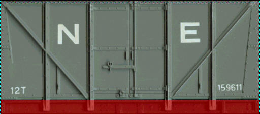
It would be nice to add some rust to the areas around the two objects we have previously created. So find your airbrush tool. PP8's airbrush is as versatile as the real thing. To control a real airbrush, you control the amount and pressure of the airflow. The analogy to this in a graphics application is pressure and transparency (opacity). These controls determine the strength of the color used and the amount of over spray. With real airbrushes, you can also control the nib opening which controls the amount of coverage; likewise a good graphics application has this feature too. To set up my airbrush in PP8, I set Size to 25 (pixels), Feathering to 100% and Pressure to 25%. Enough to give me good control over the tool. Making certain that I am working on the bottom most layer, I add a little rust to the wagon ends. I use different shades of orange and browns for rust.
Once the paint is on, you want to smudge this in a bit to make it look more natural. For this in PP8 you use the blending tool. The blending tool is very much like an airbrush except that it averages out colors instead of adding any. As with the airbrush tool, you need to use a Very light touch especially as it has the tendency to blur details. Fig 28 shows the blending in process - note I usually zoom in to be able to see what I am doing.
Revisiting the metal strip and panel we made previously, we want to add some highlights to help define their forms. Highlights can be done with the pencil tool. As with other tools in PP8, you can control the strength of the colors. Especially with white, I use this tool at 70% transparency or less. This allows me to add highlights and shadows (using black) without overwhelming the underlying colors. (See Fig 29. & 30.) Note that with shadows and highlights, the convention is to follow the "45-degree rule" - this assumes that the light is hitting the object from a 45-degree angle from your left. Keep to this rule and you will be on safe grounds.
![]()
To finish off the ends, I affix all the pieces and then adjust the total values of the entire end piece so that the tones more closely match the roof. Save the file when you're done and take a break. Fig 31. shows the completed lower half of the texture map.
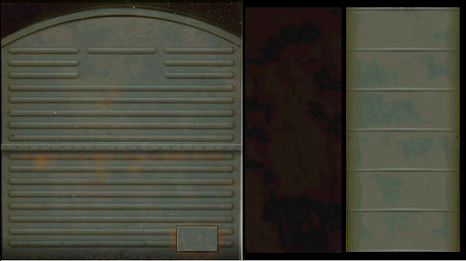
The Wagon Sides:
To do the sides properly, you will need to break up the existing into a series of separate objects. What basically needs to be done is to disassemble the image as if it was a real train panel. Work on each of the individual parts and then put everything back together again.
Begin by isolating the struts as in Fig 32. Mask these off and make it into a separate object (Layer 1).
Then mask off the main frame bracing as in Fig 33.
Make this into a separate object also (Layer 2). Finally mask off the entire side as in Fig 34. Make that a separate object (Layer 3).
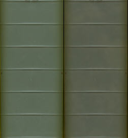
Before doing anything else sort out the object and make sure that the ribbings (Layer 1) is on the top layer and the main side panel (Layer 3) is the bottom layer (see Fig 35.)
Working Layer 3:
Refer to Fig 36. Using only the techniques as outlined for the wagon ends, gradually build up the surface characteristics of the sides. Sharpen the base image and add the texture bumping first. Then add shadows followed by highlights. Add dirt and rust last and blend everything in till it looks natural. If you know how to control luminance in your graphics application, here is as good an opportunity to use those tools (the use of which is beyond the scope of this tutorial).
Working Layers 1 & 2:
Refer to Fig 37. These two layers use the same techniques as those used on Layer 3. Only main difference was tones were kept lighter and more attention was paid to building definition of the details.
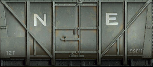
Finish off by flatting everything. Re-mask the areas just work and sharpen. Adjust the tonal values, if necessary to match with the other pieces. Then look over the entire map and do a final clean up. On the right side of the wagon end piece, there is a white vertical streak. Rebuild this area with elements on the left side of this image. Have one final look to make sure everything is as it should be. If your final map looks like Fig 38. pat yourself on the back - you've just become an expert texture artist. Finally, save the final version of the texture map and exit the program.
I use MakeACEWin to make my ACE files. Now is as good a time as any to do this. Do not allow TSM to make the ACE conversions for you as it defaults automatically to using DXT compression which will remove a good percentage of the sharpness from the finely rendered texture maps that you have just completed.
First convert 12Ta.bmp into 12Ta.ace. Select Zlib compression and save this new file into your project folder for now. Likewise convert 12Tb.tga into 12Tb.ace. Make sure to check off the �Alpha channel is one-bit transparency mask� check box before you do the conversion.
If you have TSTOOLS2 pop open the two new ace files to make sure everything is all right.
Load TSM and open 12T.dst. To avoid problems, switch over to polygon mode and make sure nothing has been selected. Now go over to point mode and make sure none of these are selected either.
Select the wheel and open up the Parts Texture Assignments panel (F4). Texture the wheel using pieces from 12T.tga. You only need to assign values to the LEFT, RIGHT, FRONT and BACK to cover the wheel. For the wheel rim, use the piece of brown texture under the buffer. Save your work. Incidentally, FRONT and BACK correlates with the wheel rim.
Copy and paste the wheel - this gives you a new wheel. Pop open the Part Properties panel for the new wheel and change the X-axis value to it's opposite equivalent. This will put the new wheel on the correct side of the wagon. Go to the Transform sub menu and rotate the new wheel on it's Y-axis by 180 degrees. Reset the wheel's pivot point orientation using the command found in the Part sub menu.
Open up the wheel's Part Properties panel and note or copy the Y-axis value. Create a new tube along the X-axis about 6 inches (0.25) in diameter and long enough to span the distance between the 2 wheels; specify only 1 section and use between 6 to 8 points. Make sure that the tube is uncapped. Open the Parts Properties panel and type in or paste the Y-axis value you previously noted. This places the axle dead center on the wheel. Select smoothing for the axle. Texture the axle using the brown texture piece on 12T.tga. You only need to specify values for FRONT and BACK.
Join to the 2 wheels and the axle and center the pivot point to the center of the new part. In the Parts Properties, make sure that smoothing is on. Select TransNorm as the material and name the new part as Wheels11.
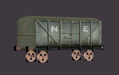
Move Wheels11 to the front of the wagon using the plan as a guide. Once it is in position copy and paste Wheels11 to create the rear set of wheels. Move the new wheels into its correct position by changing the Z-axis value into its opposite (negative) value. Rename the new wheel Wheels21. Your wagon should now look like Fig 39. Save your work.
Select and texture the buffer. Once again you will only need the FRONT, BACK, LEFT and RIGHT values. Copy and paste the buffer. Move the new buffer to its correct location by editing its X-axis value.
Join both buffers and center the new part's pivot point to the center of the new object. Copy and paste the joined pair of buffers. Move the copy to that back by editing its Z-axis value. Rotate on its Y-axis by 180 degrees and
reorientate its pivot points. Join both sets of buffers and link this to the part you previously named MAIN (the wagon body). Center the buffers' pivot point to the center of the object. Set the material to TransNorm. Save your work.
Note that the buffers need to have smoothing turned on. In TSM, this may make the buffer ends appear all black. This is OK, it will display correctly in the
sim.
Select MAIN as your current part. Texture the TOP, BOTTOM, FRONT and BACK only using the correct pieces. Your wagon should now look like Fig 40. Looking at the sides, you may be thinking "what gives" - what is happening here is that TSM is thinking of the hull as a cylinder.
Switch over to polygon mode and select the two sides. Now open up the Part Texture Assignments panel. Clear the values for TOP, BOTTOM, FRONT and BACK. Specify values for LEFT and RIGHT and close the dialog panel. Unselect all polygons. Your Wagon should now look like fig 41. Still a little off, so we will need to make some final adjustments.
Select one of the sides and go into the Polygon sub menu. Select Textures and make the final adjustments to the sides mapping using the custom option. Do the same with the other side. Your wagon should now look like fig 42. Save your work.
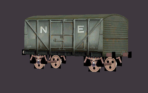
Create a box 6.25 wide, 2.5 high and 5 deep. Move this into position over the front wheel. Switch to the polygon tool and delete the front, back, top and bottom polygons. Copy the box and scale it slightly smaller constrained to the X-axis. In polygon mode flip each face inwards. Join the two newly created parts and texture LEFT and RIGHT only. Re-center the pivot point to the object's center. Name this part Bogie1 and link this to MAIN. Set the material to TransNorm. Finally select Wheel11 and link this to Bogie1.
Copy Bogie1 and paste it to create the second bogie. Name the new part bogie2 and move this to its correct position by editing the Z-axis. Link Wheel21 to Bogie2.
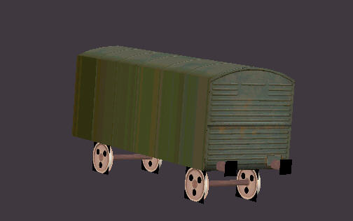
The completed model in TSM should look like Fig 43. Save your work.
Do a final check.
Links:
Wheels11 - Bogie1 - Main
Wheels21 - Bogie2 - Main
BUFFERS - MAIN
Check for un-textured polygons - there should be none.
Check for orphaned points - there should be none.
Check for part geometries - there should be no non-planar polygons
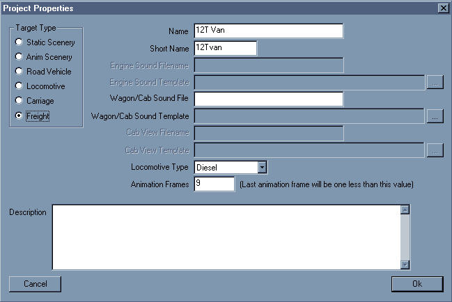
From the File sub menu, open the Project Properties box. Fill and select the options as in Fig 44. Of importance is Animation Frames. Make sure this reads 9 or your wheels will not move correctly.
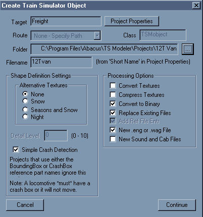
Now open up the Create Train Simulator Object dialog box. Set the folder for now to your project folder. Name the new s file 12Tvan.s.
Uncheck the boxes indicated in Fig 45. and begin the conversion process. As is, this will create a van using automatic couplers. I will leave it to you to edit the correct values into the wag files.
Create a new folder in your TRAINSET directory naming it 12Tvan. Copy the following files from your projects folder into the new folder:
12Ta.ace
12Tb.ace
12Tvan.s
12Tvan.sd
12Tvan.wag
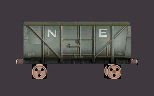
You should now be able to create a new consists using the new 12T van. Then load up MSTS and see how your project turned out. (See fig 46.) The model I made whilst developing this tutorial is also available as a separate download from the download area of this site.